 E-shop
1 button, 2 directions, 3 protection

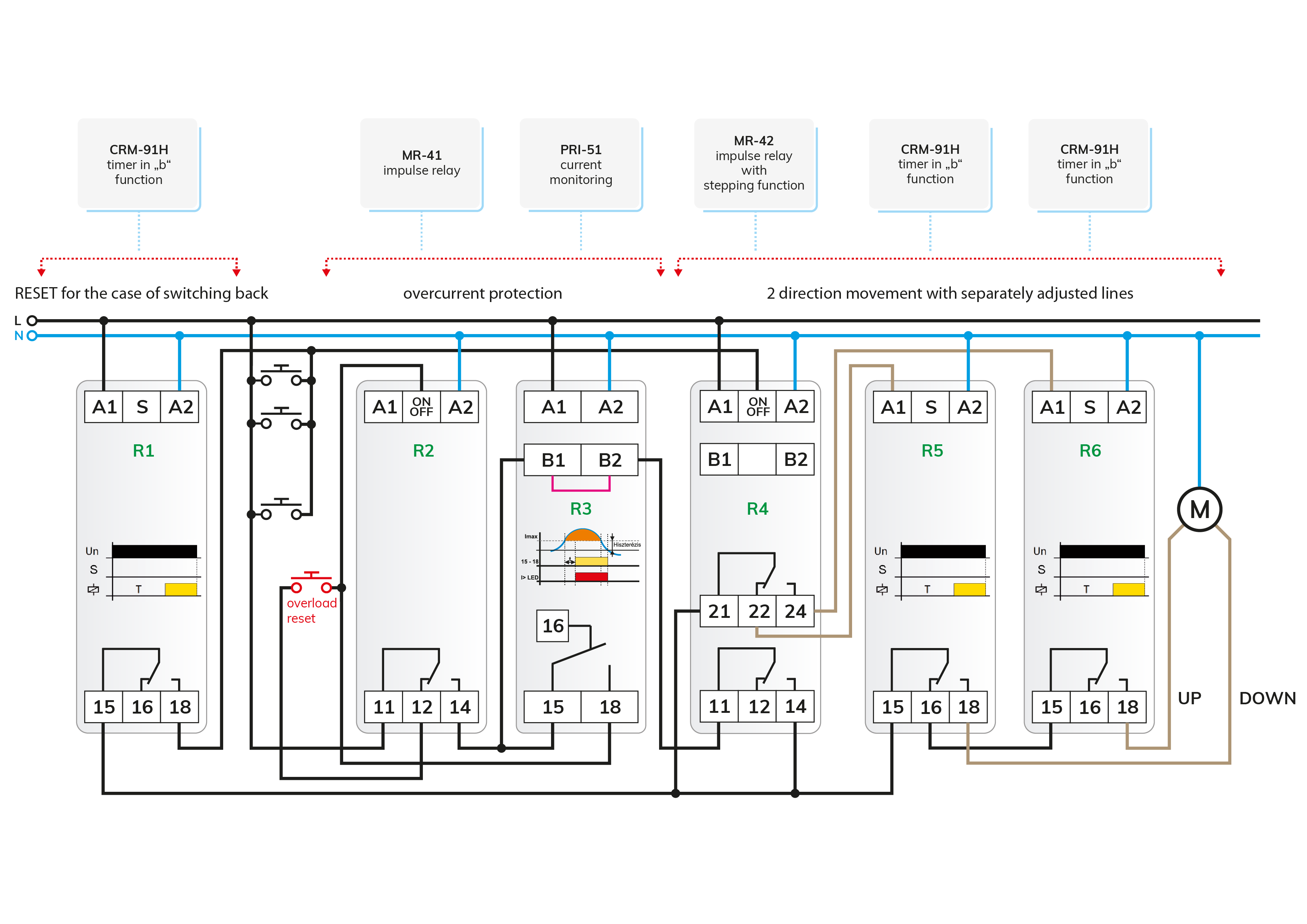
The number 1 - 2 - 3 is a coincidence in reality, but it is completely true of the relay circuit that is now being presented, which may seem a bit complicated at first. A pushbutton is sufficient to control a suitable electric motor (e.g. gate movement) in two directions, but the circuit shown in Picture 1 also has three protection functions.
In the drawing, the individual functional parts are marked separately, which can even be used as a stand-alone circuit in other applications. The basic condition is, of course, that the drive motors have their own limit switch.
Basic circuit
Operation is based on the MR-42 stepping pulse relay marked "R4", which changes state in the order of the 2-bit binary number chain each time a button is pressed (rising edge at the ON/OFF input): 01 - 10 - 11 - 00 (0= relay is off, 1= relay is on). The operation of the directional control is also illustrated in the table.
| Output 2 (21-24) | Output 1 (11-14) | Function | |
| 1st press the button | OFF | ON | UP |
| 2nd press the button | ON | OFF | STOP |
| 3rd press the button | OFF | ON | DOWN |
| 4th press the button | ON | OFF | STOP |
Protection against simultaneous switching of the two directions
The two coils of the motor must not be energized simultaneously, which is ensured by the changeover contact of the MR-42 channel 2 itself as it will normally never switch on the voltage at the same time. An additional protection can be provided by locking the changeover contacts of the two-time relays with the connection shown in the picture.
RESET after power failure
If the system was in STOP mode when the mains were switched back on after a power failure, nothing special would happen, the movement would not start automatically. If a power failure occurs during movement and then the system is reconnected to power, then channel 1 of the MR-42 will be energized and the movement could start in the direction it was moving during the power failure. To prevent this from happening, we have installed a time relay marked “R1”, which is also in function “b” and receives the common supply voltage directly. If the power is turned on, it will definitely start its delayed release and the relay will energize. Its output is connected in parallel with the pushbuttons, so the rising edge shown here can switch the MR-42 pulse relay. Because terminal 15 of “R1” receives voltage only when voltage is applied to terminal 14 of “R4” (motion enable signal), it can only switch the MR-42 pulse relay when it is in the move phase, so a STOP command must be issued to prevent the move from starting automatically.
Overcurrent protection
When the object being moved (gate, garage door, etc.) hits an obstacle or gets stuck, the motor may even burn out. As a protection, a PRI-51 / xx current monitoring relay is installed, which acts as a current limit switch: if the current flowing through the inner shunt exceeds the set value, the relay is energized. The PRI-51 series has an adjustable max. the current limit is available in several versions ("xx" in type code = max. current limit). The adjustable minimum current value is 10% of the max. as well and a delay can be set in the range of 0.5 to 10 seconds against short-term disturbances. If the PRI-51 detects an overcurrent, its relay energizes and the phase at terminal 18 switches the MR-41 pulse relay, which interrupts the motor power supply and stops moving. Restart is only possible with the "overload RESET" button after the problem that caused the overcurrent has been eliminated.
TIP
If the system is switched off due to overcurrent and then restarted with the red button, the move will start if the overcurrent has actually stopped. If you do not want to do this, you can also connect the supply voltage to "A1" of "R1" from terminal 14 of the "R2", then the movement will not start after pressing the overload RESET button, because the MR-42 pulse relay will stop.
We'll be coming up with more tricks soon.
In the meantime, we wish you pleasant, “overcurrent” - and barrier-free days!
Attention! The solutions presented in the articles are illustrated with conceptual circuit diagrams in which, despite repeated inspections or tests under workshop conditions, errors may occur. It is the installer's task and responsibility to check their suitability for a given task and to make any changes! The author and the company do not accept any liability for damages or other problems resulting from the use of the presented solutions. The colors of the wires in the drawings only help for easier transparency, they do not necessarily match the colors of the standard wiring!