We have used the pulse relay type
MR-42 many times, not only for lighting control functions. In this week's letter, we also use this versatile, simple small relay module for a simple switching technology idea - specifically for the two-way control of motors (blinds, gate or garage door operators). Of course, that would be too easy!
How should it work?
Let's use our relays in the same way as controllers manufactured specifically for this purpose. For two-way control, use only one push button (or several connected in parallel), so the operation is as follows:
- the first button press starts e.g. up the shutter
- it stops on the next button press
- another button press moves in the other direction (e.g. down)
- it stops with one more button press
… and so on, for each button press, the above sequence is carried out one after the other, even when switching back on after a power failure, since the pulse relay stores its last state.
Simple, one-button control with a single MR-42
Figure 1 illustrates the implementation of the described operation with the MR-42.
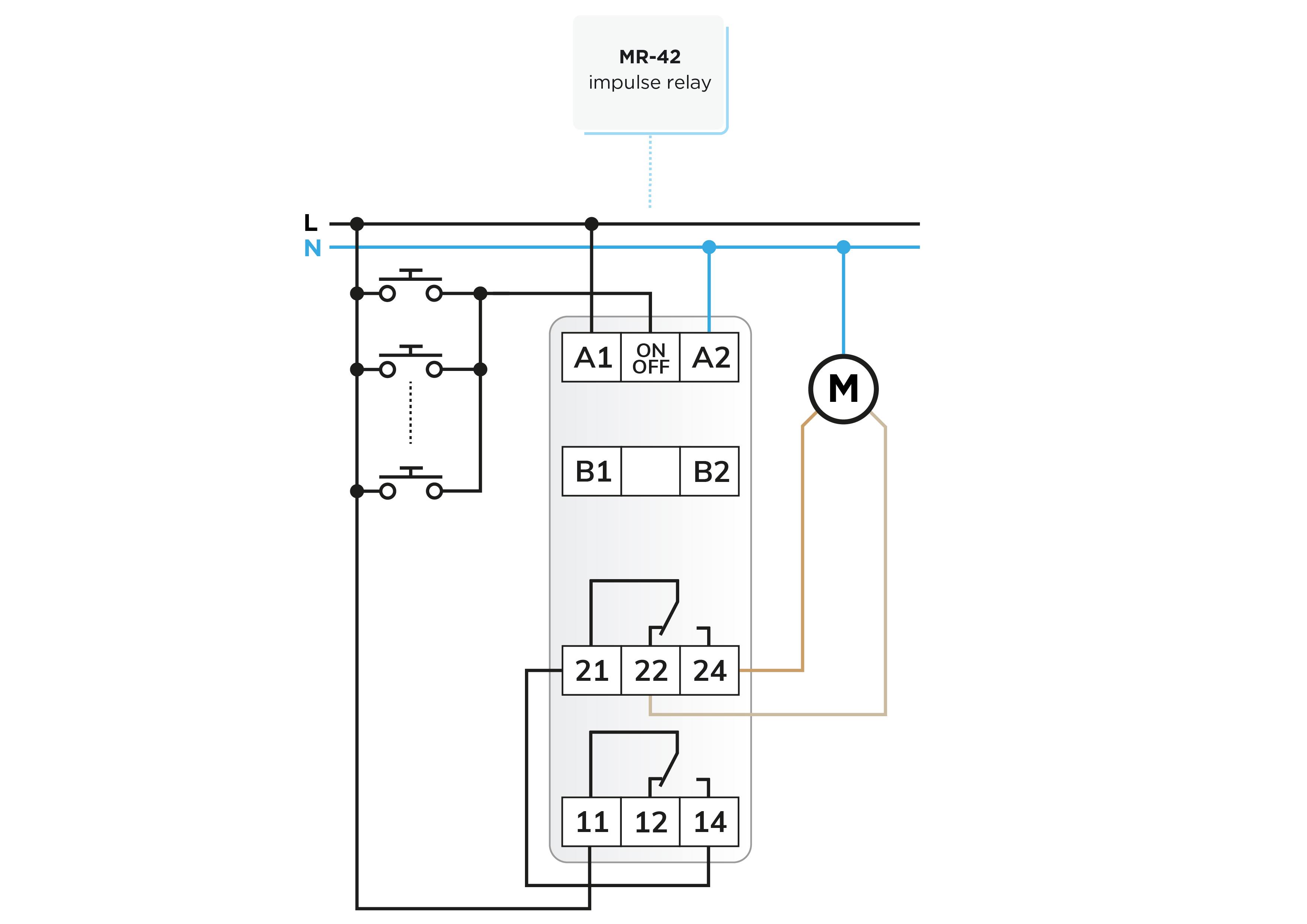
Figure 1 - click to enlarge
| |
Relay 1 |
Relay 2 |
Motion of motor |
| 1st press the button |
ON |
OFF |
UP |
| 2nd press the button |
OFF |
ON |
STOP |
| 3rd press the button |
ON |
ON |
DOWN |
| 4th press the button |
OFF |
OFF |
STOP |
In the connection, we actually did nothing but make use of the shift function of the MR-42 to create a classic relay shutter control. Channel 1 connects the power supply to the common contact (21) of the changeover contact relay of channel 2, which thus provides voltage for both directions. The direction in which the movement takes place depends on the state of channel 2: in the idle position, the power supply goes to the motor winding of one direction, and in the active position of the other direction.
From the operation of the relay, it can be seen that channel 1 switches on every second button press, which perfectly solves the power supply switching on in the sequence of button presses. The direction control is logical, since the two states of channel 2 are just right for the purpose. You could say we are ready, provided that the drive units (motors) are equipped with their own limit switches. Yes... there are factory controllers with such a simple operation, but most of them also have a timer so that the motor system does not remain under power even if it has already reached its end position.
Let's use a time relay too!
In Figure 2, we further thought about the above connection and incorporated a time relay. A single time relay may be sufficient if there is no significant difference between the durations of the movement of the two directions to the end stop (e.g. it does not get stuck more up than down or slower in the more loaded direction).
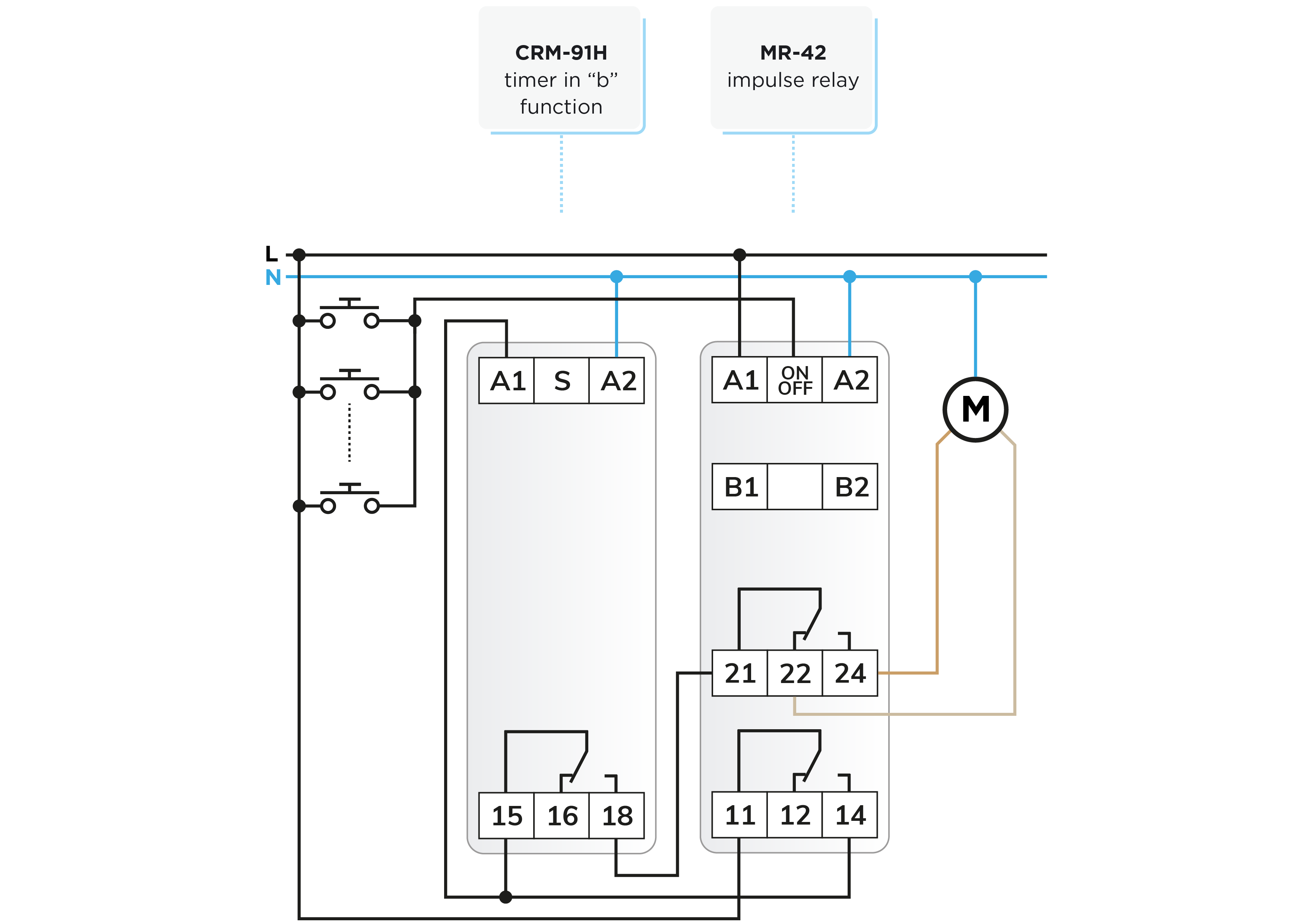
Figure 2 - click to enlarge
The function marked "b" of the
CRM-91H time relay corresponds to the purpose, which is a release delay starting with the supply voltage. In the connection, channel 1 of the MR-42 starts the time relay, whose relay is energized and switches the supply voltage to terminal 21. And after the delay, it turns off. The
CRM-161 can also be used as a time relay, also in the "b" function.
It can also be solved if the movement durations of the two directions have to be differentiated. In this case, two-time relays are needed, which work in the same "b" function, but the power is received separately from contacts 22 and 24, so the motor is switched directly by the outputs of the time relays. The connection 11-21 is then necessary.
Expansion with obstacle protection
The factory controllers are usually also equipped with torque monitoring, so if the moving gate or garage door hits an obstacle, they stop the drive and then pull the gate back a little. Anyone familiar with electronics knows that it is child's play to solve this with a so-called embedded system, a program made for a microcontroller and a target circuit. But we have relay controls, … we cook from what is in the pantry, so we implement the protection with a current monitoring relay.
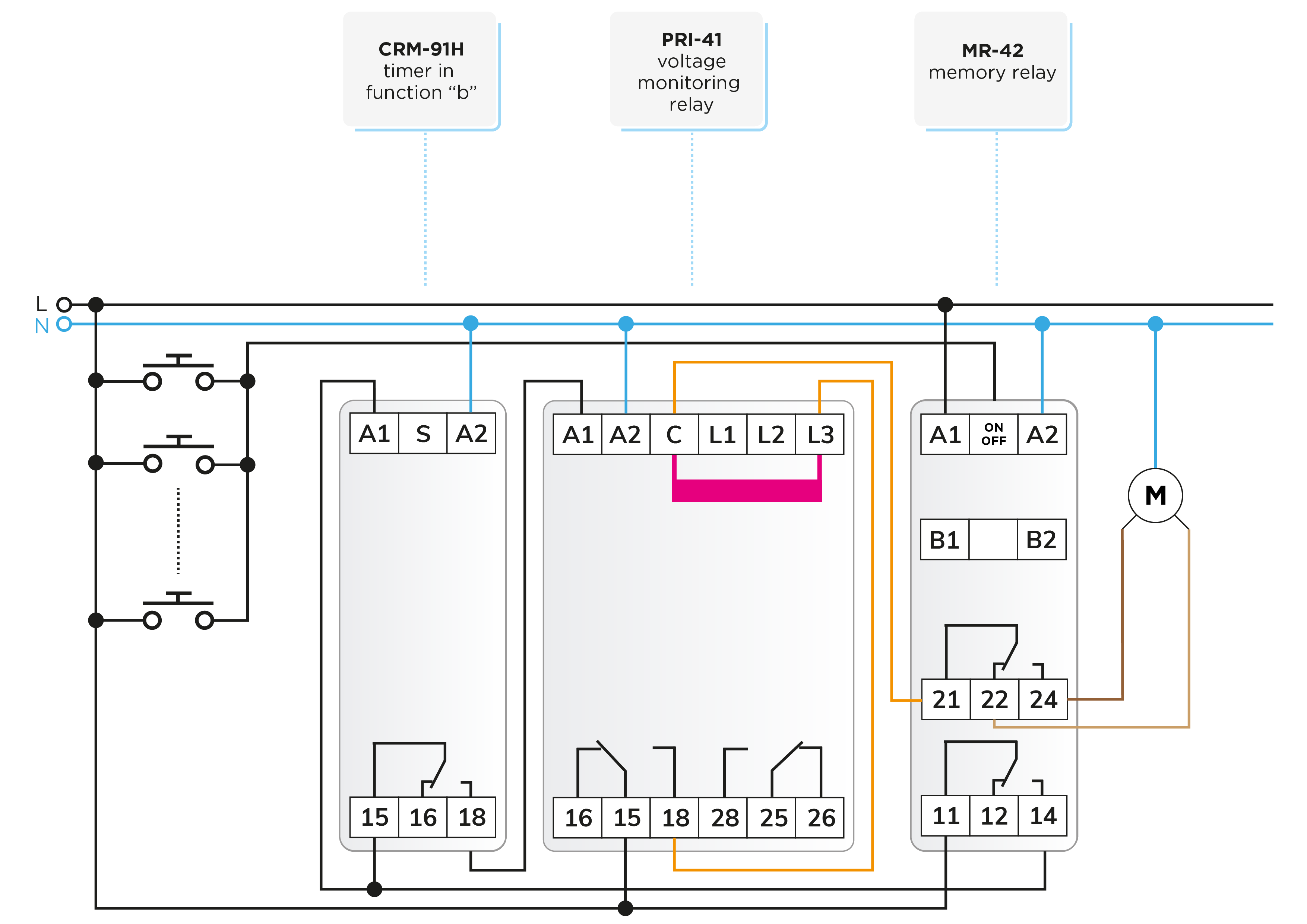
Fortunately, ELKO EP offers several types of current monitoring relays, of which we will use the PRI-41 type for this task. A possible version of the circuit diagram is shown in Figure 3.

Figure 3 - click to enlarge
Operation of the PRI-41
The PRI-41 current monitoring relay measures the consumer's current with an internal shunt, the current ranges of which can be selected with three connection options (see downloadable user manual). Here, the current of the consumer is passed through the shunt with the smallest current. The minimum and maximum current can be set, but we will only need the maximum here, but for operation, set the minimum as well.
If the monitored current is the min. - max. is in the window, both relays are closed, 15 - 18 and 25 - 28 are closed - this is the default state. If the monitored current is higher than the set maximum and this persists even after the set delay, then contacts 15 - 18 of relay 1 open, thereby stopping the drive.
For gate or garage drive motors, it comes in handy that the PRI-41 can be used for both AC and DC currents - it can be selected with a DIP switch.
Operation of the circuit
As discussed in the previous letter, the stepper relay switches the control states with button presses: LEFT, OFF, RIGHT, OFF. The CRM-91H time relay determines the movement time by switching on the supply voltage to the PRI-41 current monitor for the necessary duration, the monitored current path of which leads through its own contacts 15 - 18 and the shunt to the changeover contact of the MR-42 direction selector, and then connects to the motor.
The locking relay opens at higher current consumption. It is worth turning on the "MEMORY" function of the PRI-41 so that the current monitor cannot switch on during the timing. In this case, the lock can be released with the "RESET" button on the front panel.
Unfortunately, the picture is not complete, because the system stops for higher current consumption, but does not move the gate back. This would require even more relays and time relays, which would be beyond the point that it would be worthwhile to control the gate movement with relays. The same is the case with infrared barriers, although this is somewhat easier to design for switching. For example, the infrared barrier can be used to control a relay, which simply interrupts the supply line driving the movement in the closing direction if an obstacle is detected.
Attention! The solutions presented in the articles are illustrated with conceptual circuit diagrams in which, despite repeated inspections or tests under workshop conditions, errors may occur. It is the installer's task and responsibility to check their suitability for a given task and to make any changes! The author and the company do not accept any liability for damages or other problems resulting from the use of the presented solutions. The colors of the wires in the drawings only help for easier transparency, they do not necessarily match the colors of the standard wiring!

 E-shop