 E-shop
Don't wait for warm water.

In addition to institutions, larger buildings and office buildings, the possibility to get hot water from several places is usually also needed in family houses and flats. It is not uncommon for more than two or three rooms to get hot water. If the production of hot water is relatively further away from these taps, then the still cold water must be allowed to flow well until the hot water arrives.
In our current letter we present two solutions for timed control of the bypass branch pump for buildings with more than two hot water intakes.
Both circuits are controlled by the existing lighting switch in such a way that not only the timing of the pump operation but also it is started with a delay.
The purpose of the short delay is to prevent the lights that are switched on due to a short stay in the rooms from starting the pump immediately.. The operating time of the pump must be set as long as the hot water in the piping system turns around.
Control from three locations with relay latches
In the circuit shown in Figure 1, the three independent light switches separately turn on the lighting in their own room and provide a voltage signal to the control circuit. To ensure that the switches do not affect each other's lighting range, each switched signal controls its own auxiliary relay.In any case, three auxiliary relays with potential-free and independent output are required - here we used the type VS308K, but it is suitable e.g. also 750L / 230 V with ES-11 socket.
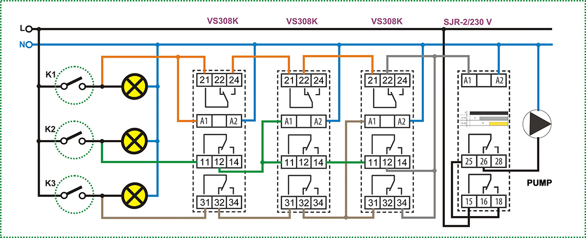
Img. no.1 - Click to enlarge image
When one switch is turned on, the associated auxiliary relay energizes and disables the control signal of the other two switches through its two disconnect contacts.
At the same time, the third closing contact of the energized auxiliary relay connects the supply voltage to the SJR-2/230 V (or / UNI) time relay, which is already well known to our regular readers.
Not used here in its basic function (timed switching of loads), but to control the delay and operating timing required for the circuit with one device. The two independently adjustable timers start simultaneously when the power supply is switched on. The duration of channel 1 "t1" will be the delay until the pump starts by switch on the lights. If the lights are turned off during this time, the process will be interrupted.
If people remain in the room, after the "t1" delay, the relay of channel 1 energizes and connects the voltage at terminal 18 to the common contact 25 of channel 2., which also appears on idle contact 26.
The pump switches on. When timer “t2” also elapses, relay 2 energizes and shuts off the pump.The operating time of the pump will therefore be the difference between the two time values, i.e. t2-t1.
An unusual but simpler solution
The direct use of electronic components is not a common, everyday practice in electrical installation. The diode is such a simple component.
We use diodes primarily for rectification, but we have already presented diode logic circuits in our letters, which have simplified the creation of OR connections.
The applicability of diodes became possible with the release of so-called UNI powered devices. Caution!
Not all manufacturers' UNI names mean what is usually included in the data sheets for ELKO UNI power supplies. A UNI power supply device is a device whose power supply can be connected to the same two power supply terminals in the AC / DC range of 12 to 240 V while maintaining full functional operation. If 230 VAC is applied to a UNI power supply via a diode, approx. half the effective voltage will be measurable at the power supply input of the device, as the diode will only pass one branch of the sine wave (it will actually be a one-way rectifier).
For mains voltage, of course, a diode with a suitable voltage must be used - here we have marked the type 1N4007, which is 1 A, 1000 V.
Figure 2 shows a really simple circuit, especially compared to the circuit of Figure 1.

Img. no.2 - Click to enlarge image
The timing is done in the same way by an SJR-2 time relay, but it is UNI powered (SJR-2 / UNI) to use diodes. With a 230 VAC powered version, the circuit does not operate due to low supply voltage and pulsating DC.
The time relay can get supply power from any switch via the diodes connected to the logic OR, so that either can start the process. If all switches (lights) are switched off during timing, the pump is switched off.
If people stay in one room for only a short time but turn on the lights in another, the process that has already started will continue without interruption and restart.
The anodes of the diodes are in the direction of the switch, the cathodes are common, so the rectified signal cannot provide reverse voltage to the other light sources.
Not even that e.g. an LED blink. It is not recommended to connect the diodes with mixed polarity, but it can also be connected to the switch with cathodes if they are all connected in the same way.
Attention! The solutions presented in the articles are illustrated with conceptual circuit diagrams in which, despite repeated inspections or tests under workshop conditions, errors may occur. It is the installer's task and responsibility to check their suitability for a given task and to make any changes! The author and the company do not accept any liability for damages or other problems resulting from the use of the presented solutions. The colors of the wires in the drawings only help for easier transparency, they do not necessarily match the colors of the standard wiring